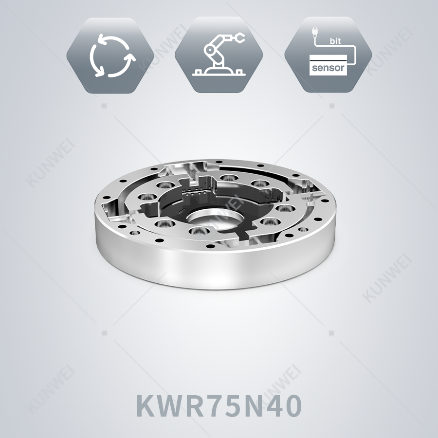
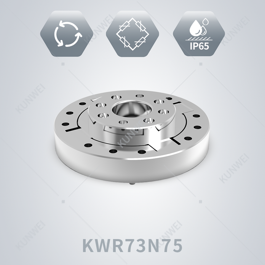
In the previous episode, we covered standard test environments and testing procedures for joint torque sensors. However, various abnormal faults are the most challenging issues encountered during on-site commissioning. Today, we will break down the most frequent problems arising in commissioning one by one, elaborate on their root causes, and walk through step-by-step troubleshooting workflows.
Issue 1: Signal Noise
After powering on the equipment, some customers observe drastic fluctuations in collected data, with waveforms resembling an electrocardiogram (ECG). Users often immediately assume the sensor is defective, yet such noise is rarely caused by failure of the sensor itself. The complete troubleshooting procedure is as follows:
- Inspect the power supply. If the sensor is powered by the joint drive board, verify power quality and voltage fluctuation amplitude. Multiple field cases have proven that replacing the power unit with a regulated power supply can significantly mitigate noise interference.
- Check grounding. Standardized grounding status and configurations exert a profound impact on digital signals. In practical applications, fully ungrounded setups turn sensor cables into equivalent antennas that pick up ambient electromagnetic interference and generate noise. When grounding is implemented, multi-point grounding must be avoided to eliminate ground loops. During the early project coordination phase, pre-plan grounding points for both the sensor and the full system, alongside the selection of sensor cables and shielded wires.
- Analyze signals by type. If power supply and grounding inspections reveal no abnormalities, conduct targeted processing based on the output signal type. Our company has accumulated extensive experience resolving noise faults for analog and digital signals, enabling us to help customers avoid such issues across diverse real-world operating conditions.
Issue 2: Zero Drift
Zero drift manifests as slow, continuous deviation in sensor readings. Most drift cases reported on-site occur under loaded operation, directly degrading measurement precision and accuracy. Two root causes are predominant among multiple contributing factors:
- Temperature effects. Ambient temperature variations and internal thermal gradients inside equipment trigger zero drift—for instance, uneven heating on two sides of the joint. If your operating conditions feature wide temperature swings, kindly inform us in advance; solutions differ greatly between scenarios with large temperature variations and steep thermal gradients.
- Mounting stress, a highly concealed trigger. Improper screw tightening sequences, uneven fastening torque, or insufficient flatness on mating mounting surfaces may yield stable readings in the initial operation stage. After prolonged runtime, gradual release and redistribution of internal structural stress will shift the zero point. We offer comprehensive testing tools and customized solutions for all zero-drift working conditions to help customers obtain authentic, accurate torque readings rapidly.
Issue 3: Inconsistent Sensitivity Between Low-Speed and High-Speed Testing
Many customers report discrepancies between torque readings captured at low and high rotational speeds. This anomaly is almost never a sensor hardware defect, but rather a flaw within the force transmission chain. If the test chain incorporates bearings, excessive bearing friction counteracts part of the applied load, resulting in sensor outputs lower than the actual torque. Furthermore, bearing friction varies with rotational speed, widening measurement deviations further. When conducting tests, shorten the force transmission path as much as possible and adopt high-stiffness, low-friction transmission structures. If on-site constraints prevent such optimizations, rest assured that our laboratory can fully replicate your application scenarios to perform in-situ calibration, improving matching performance between the sensor and actual working conditions.
Issue 4: Insufficient System Bandwidth & Poor Dynamic Performance
Torque sensors feature natural frequencies up to the kilohertz range, delivering outstanding native dynamic performance. Nevertheless, once integrated with data acquisition equipment and operated under load, the overall dynamic performance of the full system degrades substantially. This follows fundamental physical laws and does not indicate sensor malfunction. If your equipment requires high-frequency dynamic force control, provide load inertia and target bandwidth parameters during the component selection stage, and we will conduct a full system matching evaluation for you.
The above covers only four high-frequency fault types. First-time users of torque sensors may encounter various non-standard anomalies, uniformly characterized by measured signals inconsistent with expected reference values. Such faults require comprehensive analysis combining equipment operating conditions and intrinsic sensor parameters. Should you fail to locate faults via independent troubleshooting, feel free to contact us anytime. We provide 7×24-hour all-day after-sales technical support to assist you in efficient equipment commissioning.

.jpg)