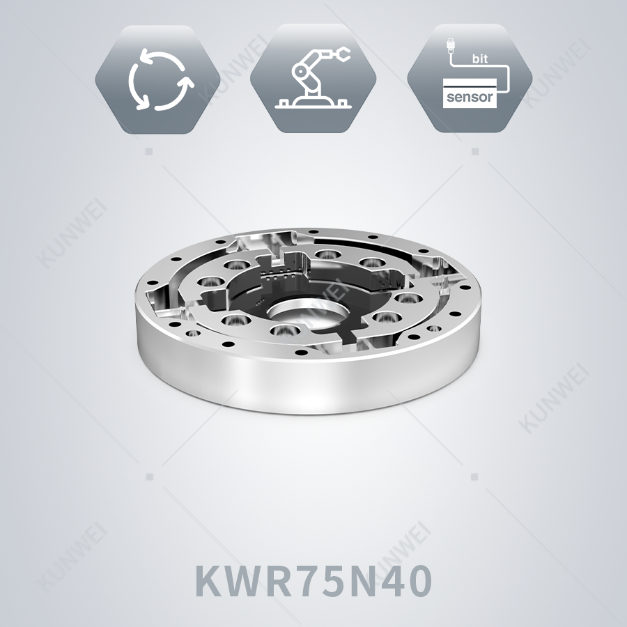
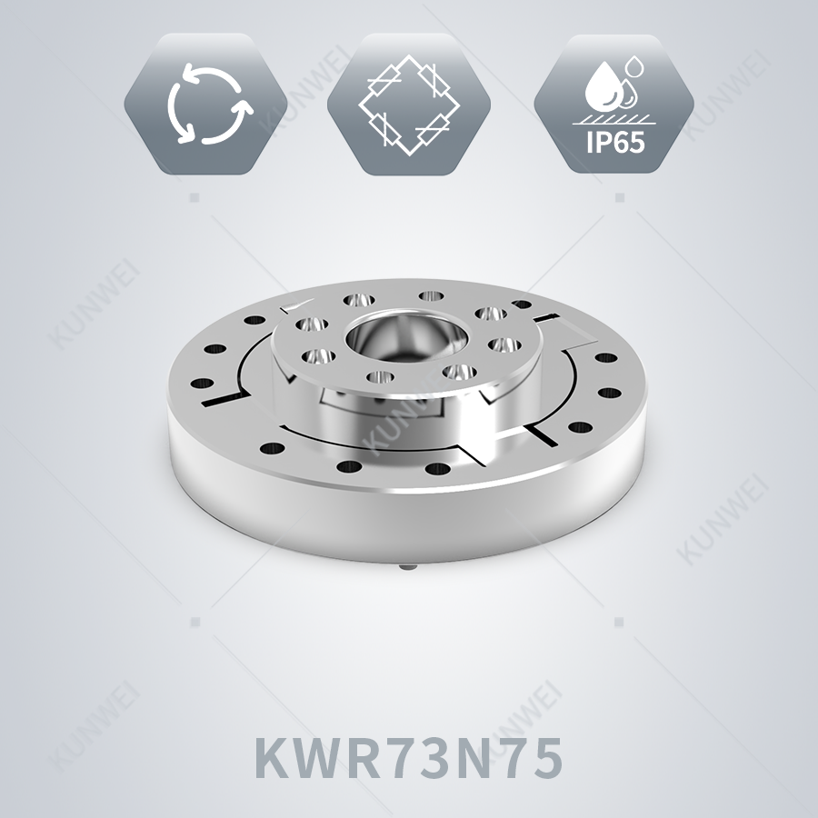
First, let’s cover the test environment. A torque sensor does not operate as an independent component. When integrated inside a joint, components such as motors and reducers will interfere with its measurement performance. We mainly recommend two testing methods.
The first method is the rocker arm method. Mount the sensor onto the joint, attach counterweights to the sensor’s output end, drive the joint to rotate forward and backward, and record data at fixed angular intervals. This method simultaneously tests the joint’s linearity and hysteresis by comparing deviations between the sensor’s output readings and theoretical torque values. It is easy to operate and capable of simulating real working conditions.
The second method is the fixed moment arm method. The sensor can either be installed on the joint or fixed separately to a base. Attach a moment arm of fixed length to the sensor, then hang different counterweights at the arm’s tip. Calculate the theoretical torque using the arm length and gravitational force, and cross-reference the figure with the sensor’s output data. This method is suitable for static calibration.
Here is a critical reminder: the connecting fixtures used for testing directly determine the accuracy of test results. If the sensor cannot be tested on the actual joint it will be fitted to and a substitute fixture has to be used, the flatness and concentricity of the fixture must match those of the real joint perfectly. Even minor unevenness on the sensor mounting surface or misalignment between the centers of the two flanges will introduce extra mounting stress. Such stress superimposes onto the genuine torque signal, leading to overstated readings or unstable measurement data. We have encountered numerous cases where customers obtained persistently out-of-spec readings with simple makeshift fixtures, yet the equipment functioned normally once installed on the official joint. For this reason, the precision of test fixtures must be equivalent to that of actual joints.
Furthermore, the sensor mounting method on the fixture must be identical to how the sensor is installed inside the real joint. Most torque sensors today suffer from insufficient boundary stiffness due to limited installation space. Calibration readings will vary under different mounting configurations. Only by adopting the same mounting method as the real application scenario can valid test results be guaranteed.

.jpg)
.jpg)