Selecting the right load cell involves making five key decisions: what force or weight needs to be measured, what level of accuracy is required, what the installation geometry is, what the operating environment is like, and what the signal/instrumentation interface is. In practice, engineers do not choose a load cell based solely on capacity; rather, they consider factors such as load direction, overload margin, resolution target, sealing level, material, and mounting constraints when selecting a load cell for a specific application, whether it be a platform scale, hopper, tank, tensile test rig, or automated production line.
The UK Weighing Federation’s (UKWF) Load Cell Guide, Rice Lake’s Load Cell and Weigh Module Handbook, and EN/industrial weighing practice all emphasise that selecting the right load cell depends on the entire weighing system, not just the sensor itself. This includes factors such as dead load, live load, side forces, shock loading, environmental exposure, and calibration requirements.
How to Select the Right Load Cell for a Project?
When reduced to a product catalogue exercise, choosing a load cell looks simple: find a capacity, pick a shape, and move on. However, in real engineering work, this approach can result in unstable readings, premature failures, poor calibration performance, or a weighing system that works on paper but not in practice. A load cell is not just a force sensor; it is the sensing core of a larger mechanical and electrical system. This means that the ‘right’ load cell is the one that fits the actual load path, the required measurement quality, the environmental conditions, the mounting method, and the electronics architecture of the project — not merely the one with a reasonable price or nominal capacity.
This is important because even when it is technically functional, a load cell can fail a project in several ways. It may saturate under shock load, drift in a washdown environment, lose accuracy if the capacity is oversized, produce poor repeatability if side loads are ignored, or be impossible to mount without introducing parasitic forces. In vessel weighing, for instance, the load cell detects not only product weight, but also dead load, piping effects, thermal expansion, agitator vibration, and, sometimes, wind or seismic forces. In a force test bench, incorrect sensor geometry can introduce bending sensitivity or off-axis error. In a compact OEM machine, cable routing, amplifier compatibility, and footprint can be just as important as rated capacity.
This is why experienced engineers usually work backwards from the application rather than forwards from the catalogue. Before selecting a single-point, shear beam, S-type, canister, pancake, or tension link load cell, they first establish what is being measured, how the force enters the structure, the smallest meaningful change in load, and the environmental or regulatory constraints. Once these questions have been answered, the shortlist becomes much narrower, and the risk of choosing the wrong sensor decreases.
Start with the Application, Not the Load Cell Shape
The first rule of selecting a load cell is simple: define the project before you define the sensor. Although a hopper scale, batching vessel, medical force fixture, truck scale, packaging line, robotic gripper force monitor, and tensile test frame may all use ‘load cells’, they do not require the same type of sensor or performance characteristics. Treating them as if they do can lead to the wrong purchase decision.
Start by describing the application in plain engineering language. Are you measuring weight or force? Is the load primarily compression, tension, bending, or a combination of directions? Is the load static, quasi-static, or dynamic? Does the load act centrally, or is off-centre loading likely? Is the sensor part of a legal-for-trade weighing system, a process control loop, a safety-related measurement, or an internal machine feedback system? These questions may sound basic, but they determine the entire selection process. For example, a floor scale with concerns about eccentric loading is not solved in the same way as a suspended tension measurement on a bagging line. Similarly, a silo support application with three mounting points would be approached differently from a compact press-fit force verification rig.
The application definition also forces you to consider how the force reaches the load cell. In theory, a load cell should only experience the intended force. In practice, however, the mechanical system often introduces side loads, torsion, uplift, thermal growth, or restraint forces from piping and supports. UKWF’s weighing guidance emphasises that weighing systems perform best when extraneous forces are minimised, made elastic, and repeatable. This point is often overlooked. Even a high-quality load cell installed in a poor mechanical system will produce poor results because the sensor faithfully measures the poor mechanics around it.
For this reason, many successful projects begin with a simple application brief containing the following information: the object being weighed or the force being measured; the total load range; the support arrangement; the expected overloads; the motion and vibration; the environmental conditions; and the required accuracy at the system level. It is only after this brief has been written that it makes sense to compare specific load cell types.
Understand the Main Load Cell Types and What They Are Good At
Once the application has been defined, the next step is to select the most suitable form factor for the load cell. Many articles are too generic at this stage, simply listing load cell types without explaining why each one exists. In practice, the geometry of a load cell is not just for show. It reflects how the sensor is designed to handle force, reject unwanted loading, and fit into a particular installation space.
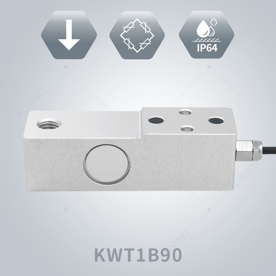
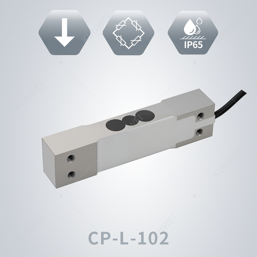
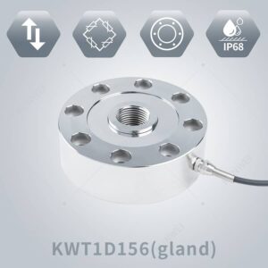
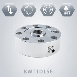
Single-point load cells are commonly found in compact platform scales, bench scales, retail scales, and OEM weighing platforms, where the sensor must tolerate off-centre loading across a defined platform size. They are attractive because one sensor can support the platform without requiring four-corner summing in small systems. Shear beam load cells are widely used in industrial platform scales, tanks, hoppers, and process weighing systems, as they are robust and accurate, and well-suited to moderate to high capacities in compression support arrangements. S-type load cells are popular for measuring both tension and compression, for example, in suspended weighing, material testing, hanging scales, and force monitoring fixtures. Canister, column, or compression load cells are commonly used in high-capacity vessel weighing, truck scales, and heavy industrial systems, where compressive loading and structural robustness are priorities. Pancake load cells are frequently used in test machines, calibration setups, and force measurement applications requiring compact axial loading with good precision. Manufacturers’ application-driven selection guides and weighing handbooks consistently recommend choosing the load cell family first based on the force path and installation style, then refining by capacity and accuracy.
The important point is that no load cell type is “best” in isolation. A shear beam cell may be excellent for a hopper support but awkward for a suspended tensile application. An S-beam may be ideal for hanging loads, but unnecessary for a four-legged vessel with compression feet. A single-point cell may simplify a benchtop scale but be completely wrong for a multi-ton silo. Good selection, therefore means resisting the urge to ask, “Which load cell is the most accurate?” and asking instead, “Which load cell geometry best matches the way this structure carries force?”
Capacity Selection: Why “Bigger Is Safer” Is Often the Wrong Strategy
If there is one mistake that appears repeatedly in real projects, it is oversizing the load cell too aggressively in the name of safety. It sounds sensible: choose a much larger capacity than needed so the cell never overloads. But load cell selection is not like choosing a thicker steel plate “just in case.” When the rated capacity is much higher than the actual operating load, the signal generated at normal working load becomes smaller relative to the full-scale range, which can reduce usable sensitivity and make it harder to achieve the required measurement resolution and repeatability.
The correct way to size a load cell is to start with the real maximum load seen by each sensor, not just the total system weight. In a vessel or platform supported by multiple load cells, that means calculating the gross weight of the structure plus contents, dividing it according to the support arrangement, and then applying a rational allowance for unequal loading, shock, overfill risk, vibration, or environmental loads. Rice Lake’s handbook recommends determining the nominal load per support and then selecting a load cell with a capacity somewhat greater than that value, often with a practical excess margin rather than an arbitrary multiple. It specifically notes factors such as inaccurate dead-load estimates, uneven distribution, agitator effects, overfilling, and wind or seismic loading as reasons capacity may need to exceed the simple nominal share.
This leads to a more disciplined rule: add engineering margin, not guesswork margin. If a tank and its maximum contents create 4,000 kg on each of four support points, selecting a 5,000 kg or 7,500 kg cell may be rational depending on loading conditions. Jumping straight to 20,000 kg “to be safe” may unnecessarily sacrifice signal quality and make the system harder to calibrate well at lower loads. The best capacity choice is therefore a balance between overload protection and usable measurement performance.
| Selection Question | Why It Matters | Typical Engineering Decision |
| What is the maximum actual load per load cell? | Prevents selecting capacity from the total system load instead of the support-point load | Calculate dead load + live load per support point |
| Will the load be evenly distributed? | Uneven loading can overload one cell before others | Add margin if the center of gravity shifts or the fill is uneven |
| Are there shock, vibration, agitator, or impact loads? | Dynamic loads may exceed static design loads | Increase capacity or redesign mounting/isolation |
| Is there a risk of overfill or misuse? | Real plants rarely operate under perfect conditions | Include rational overload allowance |
| What is the required minimum measurable increment? | Oversized cells reduce the signal at the working load | Avoid selecting far above the real operating range |
Accuracy, Resolution, and Repeatability: Define What the Project Actually Needs
Another common error when making a selection is to ask for ‘high accuracy’ without defining what this means for the project. Although a load cell supplier can provide specifications for non-linearity, hysteresis, repeatability, creep, temperature effects, safe overload, and output sensitivity, these numbers only become useful when they are tied to the application. For example, a batching system that doses raw material to a few grams, a tank inventory system that tracks bulk level changes, and a structural test fixture that measures force-displacement curves all have very different accuracy expectations.
The first distinction to be made is between load cell accuracy and system accuracy. The load cell is only one contributor to the final result. Mechanical friction, mounting error, junction box trimming, indicator resolution, excitation stability, thermal drift, and calibration method all influence the system. This is why a project should not only define the load cell specification, but also the minimum meaningful load change and the acceptable total measurement error at the application level. Hardy’s weighing guidance clearly illustrates this practical point: if a weighing system has a very large total capacity, it is unrealistic to expect extremely fine increments from a standard strain-gauge setup unless the entire instrumentation chain is designed for this purpose.
It is also important to consider where accuracy is required. Some systems require optimal performance at the upper end of the range, while others require high resolution at the lower end. For example, a bulk silo may require reliable inventory tracking for large quantities of material, whereas a benchtop filling machine may require precise control over a relatively small working range. In these cases, the same nominal load cell capacity could technically be usable in both systems, but commercially inappropriate for one of them. Rather than asking, “What is the most accurate load cell?”, the right question is, “What accuracy, repeatability, and stability are required at the actual operating load range of this project?”
Environmental and Mechanical Conditions Can Override the Catalog Specs
Even a well-sized, high-accuracy load cell can underperform if the surrounding environment is not taken into account. Load cells are used in a variety of environments, including wet washdown areas, corrosive chemical plants, outdoor silos, vibrating conveyors, hot production lines, refrigerated rooms, and mobile machinery. In these conditions, the material, sealing, cable design, and mounting protection become selection criteria that are just as important as capacity.
A load cell installed in a dry indoor laboratory, for example, may work perfectly with basic protection and standard alloy-steel construction. However, that same cell could be unsuitable for use in a food plant with daily high-pressure washdowns, a fertiliser plant with a corrosive atmosphere, or an outdoor installation exposed to condensation and temperature cycling. Rice Lake and other weighing guides emphasise the importance of stainless steel construction, hermetic sealing, and correct cable protection where corrosion, moisture, or aggressive cleaning procedures are present.
Mechanical conditions matter just as much. Side loading, uplift, pipe restraint, thermal expansion, and base-frame flexibility can all distort readings or damage the sensor over time. This is why load cell selection should always be linked to mounting hardware and installation design rather than being treated as a sensor-only purchase. In many industrial projects, the success of the weighing system depends as much on the weigh module, rocker pin, anti-lift arrangement, and vessel restraint design as it does on the cell itself.
Match the Load Cell to the Project Scenario, Not Just the Capacity
By the time you have defined the load direction, the real per-cell load, the accuracy target, and the environmental constraints, the shortlist of possible load cells becomes much more manageable. The next step is to translate those requirements into the actual project scenario. This is where selection becomes practical rather than theoretical, because different applications reward different load cell geometries and mounting strategies.
For tank, hopper, and silo weighing, engineers often prefer shear beam, double-ended shear beam, or compression/canister load cells, usually combined with purpose-built weigh modules. The reason is not just capacity. Vessel systems must handle dead load, product load, uneven filling, thermal expansion, piping forces, and sometimes wind or seismic loading. A weigh module can help keep the force path controlled while also providing lift-off protection or side restraint. In this kind of application, the load cell should not be selected separately from the mount. The real purchasing unit is often the load cell plus mounting assembly plus indicator strategy. If the vessel is tall, outdoors, or connected to rigid process piping, those secondary mechanical effects may influence the final performance more than the load cell’s headline accuracy class.
For platform scales and compact OEM weighing systems, single-point or shear beam load cells are common choices depending on size and capacity. A small bench platform often benefits from a single-point design because it can tolerate off-center loading within a defined platform size without requiring multiple sensors and corner trimming. Larger industrial floor scales may move to multiple shear beam cells because the structure is larger, the capacity is higher, and the loading pattern is less controlled. The selection question is not only “How much weight?” but also “Where on the platform will the user place that weight, and how repeatable is the load position?”
For tension measurement, suspended loads, hanging hoppers, crane-related monitoring, or material test setups, S-type load cells and tension link / inline tension sensors are often the better fit because they are naturally suited to axial tension loading and are easy to integrate into rods, shackles, or suspended assemblies. For test benches, press-force verification, and laboratory force measurement, pancake, low-profile compression, or universal force transducers may be preferable because they are designed for well-controlled axial force measurement with high repeatability and compact installation. In other words, application fit should reduce the amount of “mechanical compromise” required to install the sensor. If the structure has to be forced to accommodate the load cell, that is often a sign that the wrong load cell type was chosen.
Do Not Ignore Signal Output, Instrument Compatibility, and Electrical Architecture
A load cell is a mechanical sensor, but it becomes a usable measurement device only when paired with the right electronics chain. This is another area where projects go wrong: the engineer spends time comparing load cell capacities and sealing levels, then treats the signal side as an afterthought. In reality, the sensor output, cable length, excitation voltage, junction box strategy, amplifier resolution, and PLC or indicator compatibility all affect whether the system delivers stable, meaningful data.
Most industrial strain-gauge load cells provide an output in mV/V, which means the sensor generates a small millivolt signal proportional to the excitation voltage and applied load. That output is then read by a weighing indicator, transmitter, amplifier, or control module. The practical implication is that the total system performance depends on both the load cell and the electronics reading it. A well-selected load cell connected to a low-quality amplifier, poorly shielded cable run, or badly grounded control cabinet can still produce noisy and unstable readings. Likewise, a high-resolution digital indicator cannot rescue a badly oversized or poorly mounted load cell.
When selecting a load cell, it is worth confirming at least six electrical questions early in the project: What excitation voltage will be used? What is the rated output of the load cell? How many load cells will be connected in parallel? What is the cable length and electrical noise environment? Is the signal going to a weight indicator, a 4–20 mA / 0–10 V transmitter, or directly into a PLC weighing module? Does the application need digital compensation, legal-for-trade approval, or diagnostic features? These questions affect whether the chosen sensor will integrate cleanly into the control system or create commissioning problems later.
In multi-cell systems, the issue becomes even more important because the cells must behave consistently together. The junction box, corner correction, and excitation stability all influence system balance. For OEM machine builders, this is often where the “best” load cell on paper loses to a slightly different model that offers a more compatible output, footprint, or cable arrangement. Good selection is therefore not only about metrology; it is also about system integration.
A Practical Step-by-Step Method for Choosing a Load Cell
If you want a repeatable engineering method rather than a generic checklist, the best approach is to follow a simple sequence that forces the project requirements into a technically defensible load cell choice. In most industrial applications, the following workflow works well.
Step 1: Define the measurement objective. Decide whether the system is measuring inventory, dosing, force verification, overload detection, process control, or legal-for-trade weight. This sets the accuracy expectation and the commercial importance of the result.
Step 2: Calculate the real load at each sensor location. Include dead load, maximum product load, possible imbalance, shock, and misuse conditions. Do not size from total system load alone unless the system truly uses one load cell.
Step 3: Identify the force direction and installation geometry. Determine whether the load is compression, tension, bending, or mixed, and whether side loads or off-axis forces are likely.
Step 4: Choose the most suitable load cell family. Single-point, shear beam, S-type, canister, pancake, or specialized miniature force sensor should be selected based on the load path and mounting style.
Step 5: Define the environmental class. Check whether the sensor must survive washdown, corrosion, outdoor weather, thermal cycling, vibration, or hygienic cleaning.
Step 6: Match the electrical output to the instrumentation. Confirm mV/V output, number of cells, indicator or PLC compatibility, cable length, and shielding requirements.
Step 7: Verify system-level performance after mounting. Review not only the load cell datasheet, but also the mounting hardware, structure stiffness, restraint design, and calibration plan.
This kind of method is more reliable than choosing by catalog filters because it forces the project team to confront the actual failure modes of industrial weighing systems. It also makes vendor conversations more productive. Instead of asking a supplier, “Which load cell should I buy?” you can ask a much better question: “I have a four-leg stainless washdown hopper, 12-ton gross weight, moderate agitation, outdoor installation, and I need stable batching accuracy of ±0.1% of applied load. Which mounting arrangement and load cell family do you recommend?” That is a question a good application engineer can answer meaningfully.
| Project Type | Usually Suitable Load Cell Types | Key Selection Focus |
| Bench / compact platform scale | Single-point load cell | Off-center loading, platform size, compact integration |
| Industrial floor scale | Shear beam or double-ended shear beam | Capacity per corner, structural rigidity, and corner loading |
| Tank/hopper/silo weighing | Shear beam, canister, compression cell with a weigh module | Dead load + live load, thermal expansion, piping effects, side restraint |
| Suspended/hanging load measurement | S-type or tension link load cell | True axial tension, mounting hardware, and shock loading |
| Test bench / press-force verification | Pancake, low-profile compression, universal force sensor | Axial alignment, repeatability, signal quality, overload protection |
| OEM machine force monitoring | Miniature beam, S-type, custom compact transducer | Space constraints, dynamic response, amplifier compatibility |
FAQ: Load Cell Selection for Engineering Projects
- How do I know what load cell capacity I need?
Start by calculating the maximum real load on each individual load cell, not just the total weight of the machine, tank, or platform. Add dead load, maximum live load, likely imbalance, and a reasonable overload margin for shock or misuse. The goal is to choose a capacity high enough to survive real operating conditions but not so high that the sensor loses useful sensitivity in the normal working range.
- Which load cell is best for a tank or hopper?
For tank, hopper, and silo weighing, shear beam, double-ended shear beam, and compression/canister load cells are commonly used, usually together with weigh modules or mounting kits. The best option depends on total weight, number of supports, agitation, thermal expansion, washdown requirements, and whether the vessel is indoors or outdoors. In these applications, the mounting hardware is often as important as the load cell itself.
- What is the difference between a shear beam and an S-type load cell?
A shear beam load cell is typically used in compression support applications such as floor scales, tanks, and hoppers. An S-type load cell is commonly used where the force is applied in tension, compression, or both, especially in hanging scales, suspended vessels, and force test fixtures. The choice depends on the direction of force and the way the sensor must be mounted into the structure.
- Can I use a larger load cell than necessary just to be safe?
You can add a safety margin, but using a load cell that is far too large for the real operating load is usually not good practice. An oversized load cell produces a smaller output signal at the working load, which can reduce effective measurement resolution and make calibration less useful for low-end measurements. A better strategy is to include a rational overload allowance rather than simply choosing the biggest capacity available.
- Does IP rating or sealing really matter for load cells?
Yes. In dry indoor applications, basic protection may be enough, but in food processing, chemical plants, outdoor installations, and washdown environments, sealing, cable protection, and material selection matter a great deal. Moisture ingress, corrosion, and aggressive cleaning chemicals can shorten load cell life or cause unstable readings if the sensor is not designed for that environment.
- What information should I give a supplier when asking for a load cell recommendation?
The most useful information includes application type, total and per-support load, force direction, number of load cells, required accuracy, installation layout, environmental conditions, overload risk, and the instrumentation you plan to use. If you provide that information, a supplier can usually recommend a much more appropriate load cell than if you only ask for “a 5-ton load cell.”
Conclusion
So, how do you select the right load cell for a project? The short answer is to treat the load cell as part of a complete measurement system rather than a standalone catalogue item. The right sensor matches the real load per support point, the actual force direction, the installation geometry, the required measurement quality, the environment, and the signal chain that turns strain into usable data. Capacity is important, but it is just one factor among many, and rarely the deciding factor in whether a weighing or force-measurement system is successful in practice.
In practical engineering terms, the most reliable load cell selection process always begins with the application: what is being measured, how the load reaches the sensor, what level of accuracy the process genuinely requires, and what mechanical or environmental disturbances the system must withstand. Once these questions have been answered, choosing between single-point, shear beam, S-type, canister, or pancake load cells becomes far easier — and far more defensible. The real lesson of successful load cell selection is not to buy a sensor first and hope it fits the project later, but to define the project clearly and then choose a load cell that fits it mechanically, electrically, and operationally from day one.