Before we talk about the calibration and detection of the transducer, let’s understand what is calibration and detection.
Calibration is to obtain the parameters of the transducer internal algorithm by loading the theoretical load and recording the corresponding original signal by the sensor. That is to establish the mapping relationship between the original signal of the sensor and force.
Detection is to obtain the sensor precision and accuracy by loading the known theoretical true value and recording the measurement , then counting and comparing the difference between the measurement results and the theoretical true value. That is testing wheather the sensor is accuracy.
In short, calibration is to obtain the sensor firmware parameters, detection is to obtain the accuracy and precision of the sensor. Talk about celibration firstly.
For the multi-axis load cell, the calibration needs to consider six components at the same time.
If we only consider the four steps of ±25%, ±50%, ±75% and ±100% in the X axis direction to load and calibrate the sensor accurately(fig.1), the red point of this figure will represent calibration sample point.
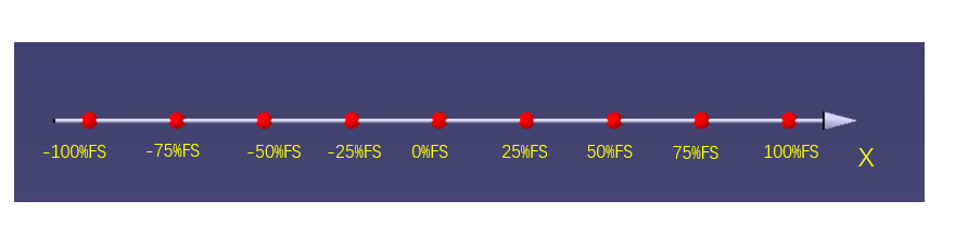
Fig.1
If the joint loading calibration of X-axis and Y-axis are considered at the same time, you will not only consider the sample point on the X-axis and Y-axis(fig.2), but also consider the other sample point on the XY plane.(fig.3 yellow points), the yellow points are also called ‘cross sample point’. Obviously, when you load the X-axis and Y-axis of the sensor jointly, the calibration sample space changes from a one-dimensional straight line to a two-dimensional plane.
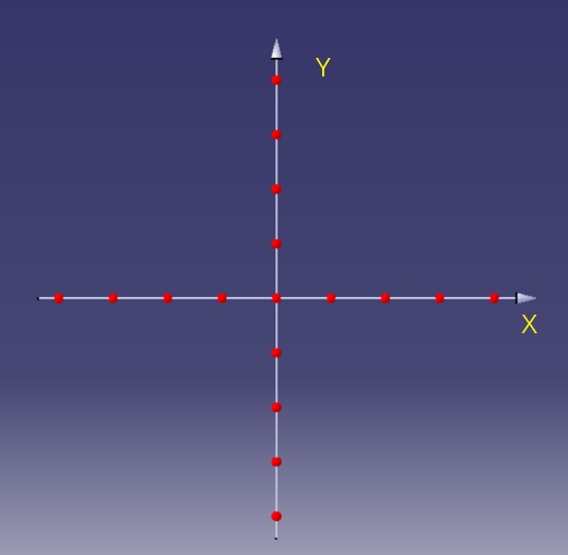
Fig.2
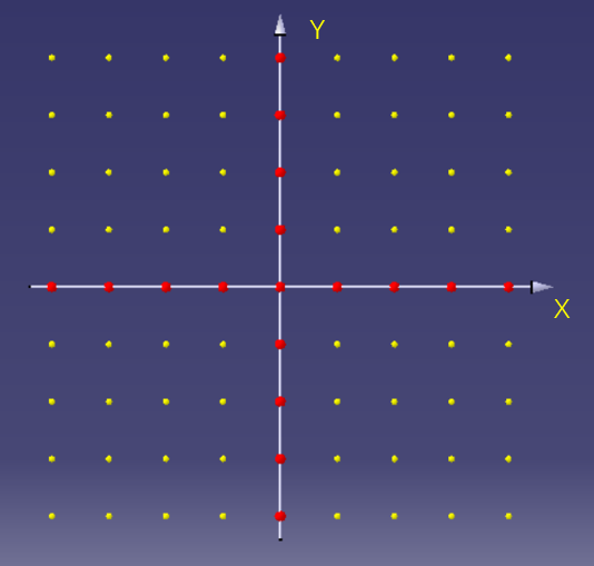
Fig.3
If you consider to load X, Y and Z three directions of the sensor jointly at the same time(fig.4), the whole loaded sample plane will become three-dimensional space(fig.5).
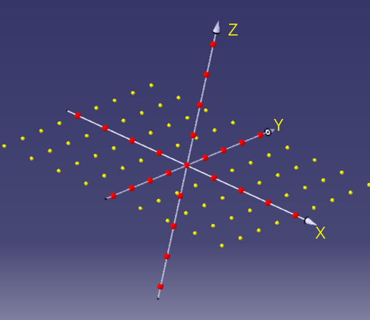
Fig.4
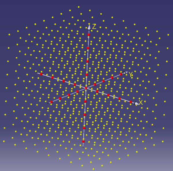
Fig.5
This kind of loading on the yellow cross-sample points outside the coordinate axis is called joint loading. In the calibration process of six-axis force/torque sensor, three directions of force and three directions of torque are loaded at the same time, which is called six-dimensional joint calibration. The 1-axis load cell, such as tension and compression load cell, just only need 9 sample points to calibrate. But if each dimensional needs 9 sample points, the six-axis force/torque sensor will include 531441 sample points(fig.6).
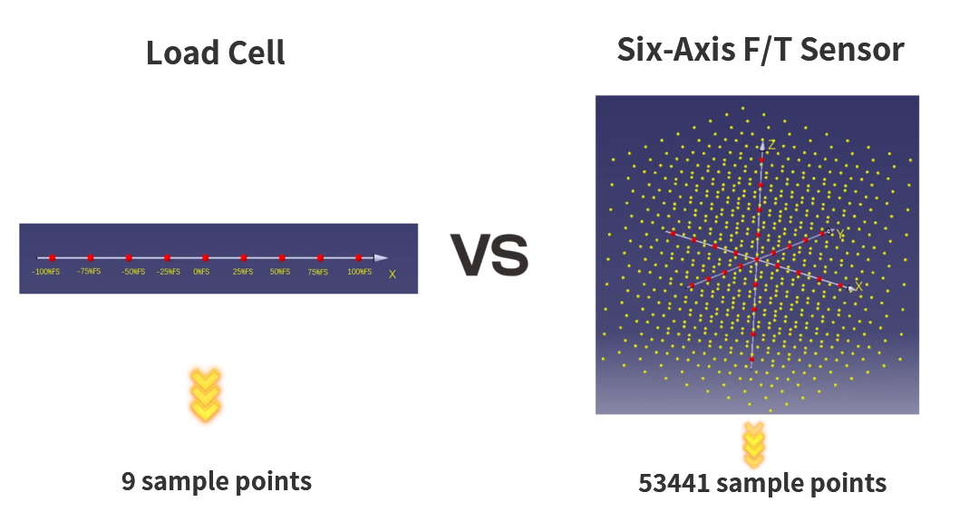
Fig.6
Using such a variety of sample points for six-dimensional joint loading calibration will bring three advantages. Firstly, the cross-sample points can make the load of the sensor simulated very close to the real usage. Secondly, it is convenient to investigate the nonlinear mechanical characteristics of the sensor under the simultaneous action of multi-axis load cell, and can immprove the design of the sensor structure effectively. Finally, the calibration based on nonlinear characristics can greatly optimized the mathematical model of decoupling algotithm.
In a word, using the calibration device of six-dimensional force joint loading, which will make the accuracy of the sensor be better and the crosstalk be lower. When the six-axis torque sensor is subjected to multiple dimensions of force at the same time, its nonlinear characteristics are very significant. The superposition of the six-dimensional linear model cannot accurately describe this nonlinear effect.
This is the whole content of this period. If you want a high-quality force measurement scheme, please pay attention to Kunwei Technology. See you next time.
.jpg)